Technical Support
Phone/WeChat: 13001715332
Please install Sunflower Remote Control software in advance.
Contact during working hours on weekdays. Thank you.
General Usage Instructions
This product series follows the MODBUS protocol. Available command codes:
0x03: Read multiple registers
0x06: Write single register
0x10: Write multiple registers
CRC Checksum: Low byte first, high byte last.
Examples:
Read Multiple Registers (Command 0x03)
0x01 0x03 0x00 0x00 0x00 0x03 0x05 0xCB
(Read 3 consecutive registers starting from address 0x0000 on device 0x0001)Write Single Register (Command 0x06)
0x01 0x06 0x00 0x01 0x00 0x01 0x19 0xCA
(Write 0x0001 to register 0x0001 on device 0x0001)Write Multiple Registers (Command 0x10)
0x01 0x10 0x00 0x00 0x00 0x02 0x04 0x00 0x00 0x00 0x01 0x32 0x6F
(Write 0x0000 to register 0x0000 and 0x0001 to register 0x0001 on device 0x0001)
Common Commands
Function: Change device address to 3
Command:01 06 00 01 00 02 59 CB
Communication Data Examples
Example 1: Read Single Holding Register (Instantaneous Flow for Mod X0)
Command:0x01 0x03 0x00 0x11 0x00 0x01 0xD4 0x0F (Hex) or 01 03 00 11 00 01 D4 0F (Dec)
Device ID: 01
Function Code: 03
Start Address: 00 11 (Hex) = 17 (Dec)
Register Count: 00 01 (1 register)
CRC Checksum: D4 0F (low byte first)
Example 2: Write Single Holding Register (Change Device Address to 2)
Command:0x01 0x06 0x00 0x01 0x00 0x02 0x59 0xCB (Hex) or 01 06 00 01 00 02 59 CB (Dec)
Device ID: 01
Function Code: 06
Start Address: 00 01 (Hex) = 1 (Dec)
Target Value: 00 02 (Hex) = 2 (Dec)
CRC Checksum: 59 CB (low byte first)
Note: The read value must be divided by 100 to obtain the actual instantaneous flow rate (unit: L/min).
Default Device Parameters
Baud Rate: 9600 (Decimal)
MODBUS Address: 1 (Decimal)
Flow Meter Constant (K): 500 (Decimal)
Data Bits: 8
Stop Bits: 1
Parity: None
General Technical Specifications
Power Supply: DC 5-24V (some models support 5-12V; refer to the label).
Note: The output voltage matches the input. Ensure the flow sensor's operating voltage range is not exceeded to avoid damage.
Dimensions & Weight
Model | Dimensions (cm) | Weight (g) | Input | Output |
Mod X0 | 82×54×32 | 61 | 1 flow sensor | None |
Mod X1T | 82×54×32 | 61 | 1 flow + 1 temp sensor | None |
Mod FPM | 82×54×32 | 61 | 1 flow + 1 pressure sensor | None |
Mod X420 | 82×54×32 | 65 | 1 flow sensor | 4-20mA |
Mod X1 | 82×54×32 | 60 | 1 flow + 1 temp + 1 pressure | None |
Mod X2 | 82×54×32 | 63 | 2 flow sensors | None |
Mod X4 | 93×90×40 | 130 | 4 flow sensors | None |
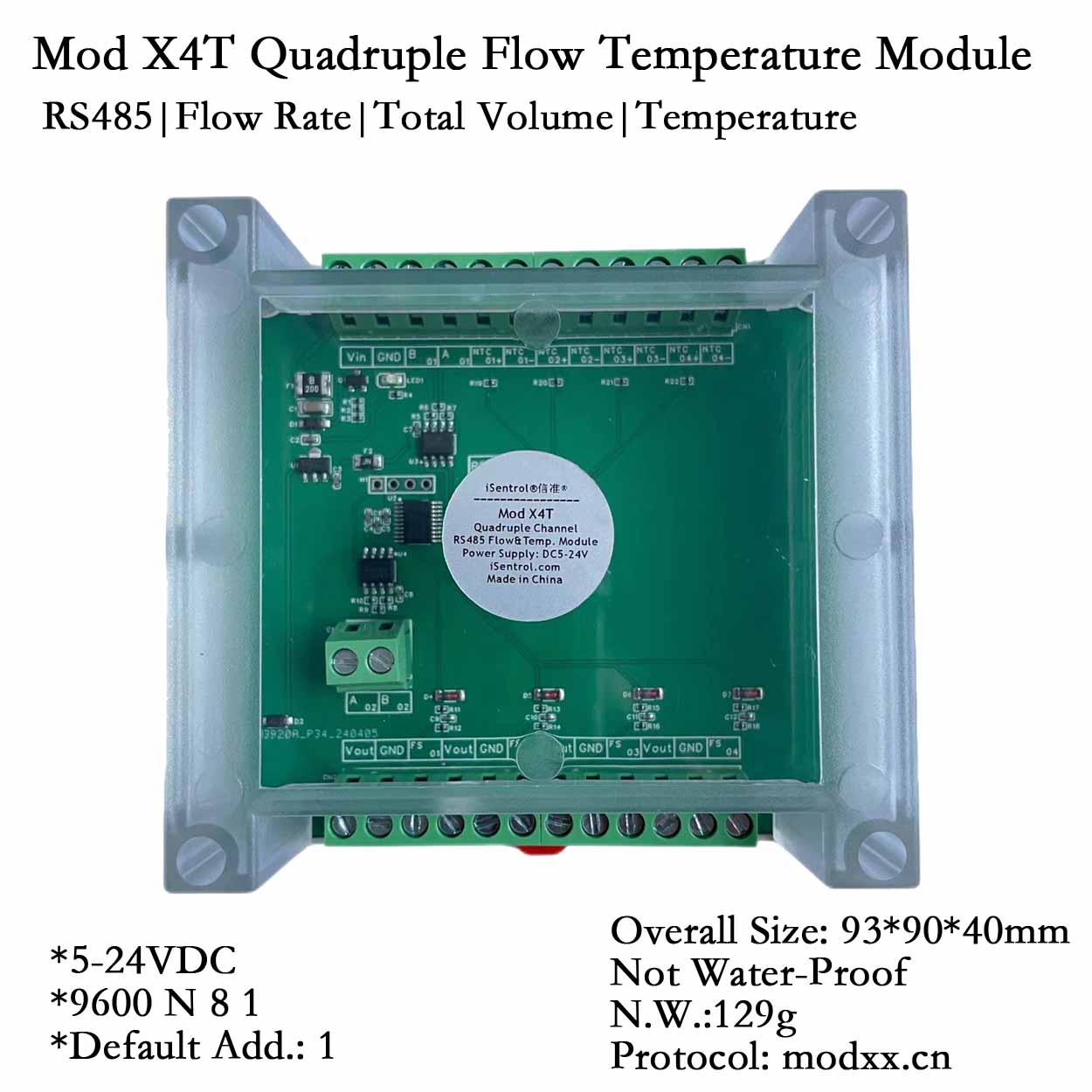
Mod X4T | 93×90×40 | 130 | 4 flow + 4 temp sensors | None |
Mod X8 | 93×90×40 | 130 | 8 flow sensors | None |
Mod X14 | 155×110×60 | 254 | 14 flow sensors | None |
Baud Rate Configuration
Default: 9600 (read value = 2).
To modify, use the following parameters (invalid values revert to 9600 but display the modified value):
Register Value | Baud Rate |
0 | 2400 |
1 | 4800 |
2 | 9600 |
3 | 19200 |
4 | 115200 |
Important Notes
Changes to address, baud rate, K value, or permanent totalizer require a device reboot.
Clear totalizer only after stopping flow to prevent post-clearance updates.
Temporary totalizer resets after power-off; permanent totalizer updates every 60s (records only if flow >1L within 60s).
Register overflow: When the low register (max 65535) overflows, the high register increments by 1.
Example: High = 1, Low = 2 → Total = 65535×1 + 2 = 65537L.
Max storage per register: 65535. Max cumulative flow per sensor: 65535×65535 + 65535 = 4,294,901,760L.
Clearing permanent totalizer: Registers 4/5/6/7 must be cleared simultaneously. Same applies to temporary totalizer.
Reset to factory defaults: Press and hold the RESET button while powering on for 10 seconds.
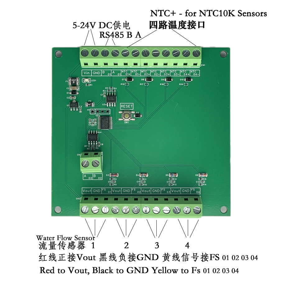
Wiring Guide
Software Tools
Modbus Debug Assistant:
Download: http://blog.mthings.cc/?id=8
iotmate (Free MODBUS Host Software):
Download: https://iotmate.cn
Protocol
Hex Address | PLC Address | Default | Description | R/W | Unit | Max Value |
0x0000 | 40001 | 2 | Baud Rate | R/W | - | 4 |
0x0001 | 40002 | 1 | Device Address | R/W | - | 247 |
0x0002 | 40003 | 2 | Decimal places | R/W | - | 3 |
0x0003 | 40004 | 500 | Flow 1 K factor (×100) | R/W | - | 65535 |
0x0004 | 40005 | - | Flow 1 permanent totalizer high | R/W | L | 65535 |
0x0005 | 40006 | - | Flow 1 permanent totalizer low | R/W | L | 65535 |
0x0006 | 40007 | - | Flow 1 permanent decimal (×100) | R/W | L | 99 |
0x0007 | 40008 | - | Flow 1 permanent pulse count for decimal register | R | Hz | 65535 |
0x0008 | 40009 | 10000 | Temp 1 resistance (B=3950) | R/W | Ω | 50000 |
0x0009 | 40010 | - | Flow 2 K factor (×100) | R/W | - | 65535 |
0x000A | 40011 | - | Flow 2 permanent totalizer high | R/W | L | 65535 |
0x000B | 40012 | - | Flow 2 permanent totalizer low | R/W | L | 65535 |
0x000C | 40013 | - | Flow 2 permanent decimal (×100) | R/W | L | 99 |
0x000D | 40014 | - | Flow 2 permanent pulse count for decimal register | R | Hz | 65535 |
0x000E | 40015 | 10000 | Temp 2 resistance (B=3950) | R/W | Ω | 50000 |
0x000F | 40016 | - | Flow 3 K factor (×100) | R/W | - | 65535 |
0x0010 | 40017 | - | Flow 3 permanent totalizer high | R/W | L | 65535 |
0x0011 | 40018 | - | Flow 3 permanent totalizer low | R/W | L | 65535 |
0x0012 | 40019 | - | Flow 3 permanent decimal (×100) | R/W | L | 99 |
0x0013 | 40020 | - | Flow 3 permanent pulse count for decimal register | R | Hz | 65535 |
0x0014 | 40021 | 10000 | Temp 3 resistance (B=3950) | R/W | Ω | 50000 |
0x0015 | 40022 | - | Flow 4 K factor (×100) | R/W | - | 65535 |
0x0016 | 40023 | - | Flow 4 permanent totalizer high | R/W | L | 65535 |
0x0017 | 40024 | - | Flow 4 permanent totalizer low | R/W | L | 65535 |
0x0018 | 40025 | - | Flow 4 permanent decimal (×100) | R/W | L | 99 |
0x0019 | 40026 | - | Flow 4 permanent pulse count for decimal register | R | Hz | 65535 |
0x001A | 40027 | 10000 | Temp 4 resistance (B=3950) | R/W | Ω | 50000 |
0x001B | 40028 | - | Flow 1 temporary totalizer high | R/W | L | 65535 |
0x001C | 40029 | - | Flow 1 temporary totalizer low | R/W | L | 65535 |
0x001D | 40030 | - | Flow 1 temporary decimal (×100) | R/W | L | 99 |
0x001E | 40031 | - | Flow 1 temporary pulse count for decimal register | R | Hz | 65535 |
0x001F | 40032 | - | Flow 1 instantaneous flow (×100) | R | L/min | 65535 |
0x0020 | 40033 | - | Flow 1 real-time pulses (×100) | R | Hz | 65535 |
0x0021 | 40034 | - | Temp 1 reading (×100) | R/W | ℃ | 65535 |
0x0022 | 40035 | - | Flow 2 temporary totalizer high | R/W | L | 65535 |
0x0023 | 40036 | - | Flow 2 temporary totalizer low | R/W | L | 65535 |
0x0024 | 40037 | - | Flow 2 temporary decimal (×100) | R/W | L | 99 |
0x0025 | 40038 | - | Flow 2 temporary pulse count for decimal register | R | Hz | 65535 |
0x0026 | 40039 | - | Flow 2 instantaneous flow (×100) | R | L/min | 65535 |
0x0027 | 40040 | - | Flow 2 real-time pulses (×100) | R | Hz | 65535 |
0x0028 | 40041 | - | Temp 2 reading (×100) | R/W | ℃ | 65535 |
0x0029 | 40042 | - | Flow 3 temporary totalizer high | R/W | L | 65535 |
0x002A | 40043 | - | Flow 3 temporary totalizer low | R/W | L | 65535 |
0x002B | 40044 | - | Flow 3 temporary decimal (×100) | R/W | L | 99 |
0x002C | 40045 | - | Flow 3 temporary pulse countfor decimal register | R | Hz | 65535 |
0x002D | 40046 | - | Flow 3 instantaneous flow (×100) | R | L/min | 65535 |
0x002E | 40047 | - | Flow 3 real-time pulses (×100) | R | Hz | 65535 |
0x002F | 40048 | - | Temp 3 reading (×100) | R/W | ℃ | 65535 |
0x0030 | 40049 | - | Flow 4 temporary totalizer high | R/W | L | 65535 |
0x0031 | 40050 | - | Flow 4 temporary totalizer low | R/W | L | 65535 |
0x0032 | 40051 | - | Flow 4 temporary decimal (×100) | R/W | L | 99 |
0x0033 | 40052 | - | Flow 4 temporary pulse count for decimal register | R | Hz | 65535 |
0x0034 | 40053 | - | Flow 4 instantaneous flow (×100) | R | L/min | 65535 |
0x0035 | 40054 | - | Flow 4 real-time pulses (×100) | R | Hz | 65535 |
0x0036 | 40055 | - | Temp 4 reading (×100) | R | ℃ | 65535 |